Why PZT Polarization Direction Is a Key Part of Structure Design
PZT polarization direction is one of the basic details that must be confirmed when designing a custom piezoelectric ceramic component. For PZT discs, rings, plates, tubes, or special-shaped parts, geometry and dimensions describe only the physical boundary. They do not explain the main direction of piezoelectric response.
Even when the same PZT material is used, a different polarization direction, electrode layout, or vibration mode can lead to a different output direction, resonance behavior, test method, and assembly requirement. In custom PZT design, polarization direction should therefore be confirmed together with dimensions, tolerances, electrodes, and the intended vibration mode.
Polarization direction determines the main piezoelectric response
After polarization, a PZT ceramic develops its primary piezoelectric response along a defined direction. This direction affects how parameters such as d33, d31, and d15 are interpreted in the final component structure.
For example, a thickness-poled disc is often evaluated for thickness-direction response. If the structure works mainly through lateral strain or bending motion, d31 and boundary conditions may become more relevant. Material parameters only become meaningful when they are read together with polarization direction and structure mode.
Dimensions alone are not enough for custom design
If a quotation request includes only diameter, thickness, inner diameter, outer diameter, or length, the supplier may not be able to determine whether the component can produce the intended motion or vibration mode.
A PZT disc may be used for sensing, actuation, atomization, or ultrasonic applications, but each use may require a different polarization direction, electrode layout, or frequency mode. A PZT ring may be used in a bolt-clamped transducer or in another ring-shaped structure. Without polarization and electrode information, the design can easily be misunderstood.
Polarization affects manufacturing, testing, and assembly
Polarization direction affects not only performance, but also manufacturing, testing, and assembly. Electrode position, positive and negative marking, soldering location, edge insulation, and test direction are all related to polarization design.
For non-standard geometries, segmented electrodes, tubular structures, or special-shaped PZT parts, polarization direction and electrode layout should be confirmed early. Otherwise, the sample may not drive as expected, may be difficult to test, or may create short-circuit risks after assembly.
What Is PZT Polarization Direction?
In engineering terms, PZT polarization direction is the direction in which the ceramic develops its main piezoelectric response after the polarization process. During polarization, a strong electric field is applied across the ceramic electrodes, aligning internal domains in a preferred direction.
PI’s technical documentation explains that the 3-axis, or direction of polarization, is established by applying a strong electric field between two electrodes during the polarization process.
Polarization direction and electrode surface are not the same thing
Electrodes are used to apply the electric field and connect the component to the circuit. Polarization direction is usually related to the direction of the electric field during polarization. In many common PZT discs or plates, the electrodes are placed on the top and bottom surfaces, and the polarization direction is along the thickness. This makes the two concepts easy to confuse.
However, in design communication, “the surface with electrodes” is not a complete polarization specification. For PZT tubes, segmented electrodes, partial electrodes, or special-shaped parts, electrode area, polarization direction, polarity, and effective working region should be clearly marked.
Common types of polarization direction
Common polarization directions in custom PZT components include thickness polarization, radial polarization, axial polarization, length-direction polarization, and shear-related polarization.
In a quotation request, it is not always necessary to describe every theoretical detail. What matters is to explain which direction the component is expected to move, sense, or vibrate. If the technical term is uncertain, a simple drawing with arrows is often more useful than an ambiguous description.
Common Polarization Methods for PZT Discs
PZT discs are among the most common piezoelectric ceramic structures. They are widely used in sensing, actuation, atomization, buzzers, and some ultrasonic applications. For disc structures, thickness polarization is the most common design.
Thickness polarization is the most common design
A typical PZT disc has electrodes on the two circular faces and is polarized through the thickness. This design makes it practical to apply the electric field and to test capacitance, d33, frequency, and impedance.
This structure is suitable for many thickness-mode, sensing, actuation, and low- to medium-power applications. Whether it is suitable for a specific device still depends on disc diameter, thickness, frequency, material, boundary conditions, and assembly method.
Polarization direction and vibration mode should be separated
A thickness-poled disc does not necessarily operate only in thickness mode. PZT discs may also show radial, bending, or coupled vibration behavior. The actual working mode depends on diameter-to-thickness ratio, electrode coverage, assembly boundary, and drive frequency.
When designing a PZT disc, both polarization direction and target vibration mode should be described. A request for “a PZT disc with a certain diameter and thickness” is not enough if the application and frequency are not specified.
What to mark on a PZT disc drawing
A PZT disc drawing should ideally include diameter, thickness, dimensional tolerance, electrode surfaces, polarization direction, positive and negative marking, edge insulation if required, soldering position, and target frequency.
If the disc will be bonded, clamped, or assembled into a metal structure, the assembly method and effective working area should also be specified. For atomization, ultrasonic, or sensing applications, it is also important to distinguish ceramic free-state frequency from the operating frequency after assembly.
Common Polarization Methods for PZT Rings
PZT rings are often used in power ultrasound, bolt-clamped transducers, stacked structures, and other piezoelectric designs that require a center hole. Compared with discs, rings require additional attention to inner diameter, outer diameter, center hole, electrode boundary, and assembly clearance.
PZT rings are often thickness-poled or axially related
Many PZT rings have electrodes on the two flat faces and are polarized through the thickness. This type of structure is common in stacked or clamped assemblies, where the electric field drives an axial response.
However, the final design still depends on how the ring will be used. In some special structures, polarization direction, electrode area, and vibration mode need to be confirmed according to the intended motion.
Ring design must consider inner diameter, outer diameter, and electrode area
The inner diameter, outer diameter, thickness, electrode coverage, edge insulation, flatness, and parallelism of a PZT ring all affect assembly and performance. The center hole requires special attention to electrode clearance and insulation distance, especially when a metal bolt or fitting passes through it.
If several rings are stacked together, the electrode connection method, polarization direction, alternate stacking arrangement, and contact surface quality should also be confirmed.
Preload changes the actual working condition of a ring
In a bolt-clamped transducer, the PZT ring does not work as a free ceramic part. Preload, metal end masses, contact surface quality, stacking method, and insulation layers can all affect actual frequency, impedance, and output.
For this reason, polarization direction and electrode layout should be designed together with the assembly structure, not only according to the ceramic dimensions.
PZT Tube Polarization and Inner/Outer Electrodes
PZT tubes are used when a tubular geometry, radial response, or special actuation method is required. Compared with discs and rings, the polarization and electrode design of a PZT tube usually depends more heavily on the specific structure.
PZT tubes may use radial or axial polarization
Common PZT tube designs include radial polarization and axial polarization. Radial polarization is often associated with inner and outer electrodes, where the electric field is applied across the tube wall. Axial or length-direction designs need to be confirmed separately based on dimensions, electrode design, and manufacturing feasibility.
For long, thin, small-bore, or thin-wall tubes, polarization and electrode manufacturing may become more difficult. Outer diameter, inner diameter, wall thickness, length, and electrode connection method should be confirmed early in the design stage.
Inner and outer electrodes affect drive direction and connection
In a tubular structure, inner and outer electrodes directly affect electric field distribution, drive direction, effective working area, soldering method, and assembly connection.
If the tube requires segmented drive or complex motion control, the electrode layout should be described with a detailed drawing. Providing only “PZT tube” with outer diameter, inner diameter, and length is usually not enough for accurate manufacturing.
What to mark on a PZT tube drawing
A PZT tube drawing should include outer diameter, inner diameter, wall thickness, length, dimensional tolerances, electrode location, polarization direction, inner and outer electrode connection method, segmented electrodes if required, and any non-electrode areas.
If the tube needs to be assembled with metal parts, fluid channels, or other structures, the assembly surfaces, insulation requirements, and soldering locations should also be defined.
How Electrode Layout Affects the Driving Method
Electrodes are not just conductive layers. They determine how the electric field is applied to the ceramic and affect the effective working area, soldering method, insulation distance, and assembly reliability.
Electrodes are not only for electrical connection
If the electrode layout is not appropriate, the electric field may not be distributed as intended. The component may have insufficient effective drive area, local electric-field concentration, difficult soldering, or short-circuit risk during assembly. These issues become more important in high-voltage, high-power, or small-size structures.
Electrode design should therefore be considered together with polarization direction, target vibration mode, and assembly method. A drawing that only says “silver electrode” or “standard electrode” may not provide enough information.
Common electrode layout types
Common electrode layouts include double-sided electrodes, inner/outer electrodes, segmented electrodes, ring electrodes, side electrodes, and partial electrodes.
Double-sided electrodes are common in discs, plates, and rings. Inner and outer electrodes are common in tube structures. Segmented electrodes are used for localized actuation or multi-channel control. Ring electrodes and partial electrodes are often used for special connection, insulation, or assembly requirements.
Electrode design should consider soldering and assembly
Electrode design should define soldering location, lead direction, insulation distance, electrode boundary, edge clearance, and metal contact areas. If a soldering point is too close to an edge, hole, or metal assembly surface, it may increase the risk of short circuit, electrode peeling, or assembly interference.
For high-power or high-voltage applications, electrode-edge discharge, local heating, and insufficient insulation distance should also be avoided.
Relationship Between Vibration Mode and Polarization Direction
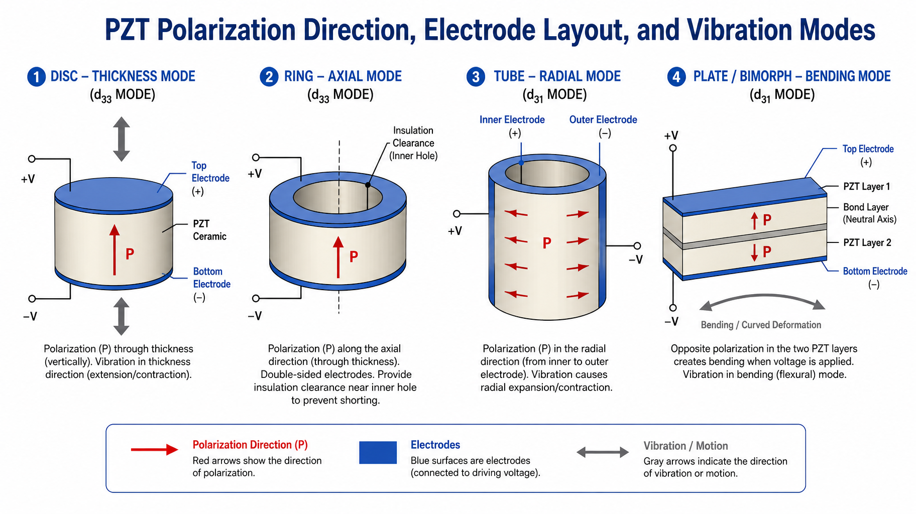
PZT structure design should start with the target vibration mode, then determine the polarization direction and electrode layout. Thickness mode, radial mode, longitudinal mode, bending mode, and shear mode may require different design choices.
American Piezo’s explanation of piezoelectric constants also shows that the subscripts in piezoelectric constants are related to electric-field direction and mechanical response direction. This is why d33, d31, d15, kp, kt, and k33 should not be interpreted without considering the structure mode.
Common vibration modes and related parameters
| Vibration mode | Common structures | Related polarization/electrode design | Commonly reviewed parameters |
|---|---|---|---|
| Thickness mode | Discs, plates, rings | Thickness polarization, double-sided electrodes | d33, kt |
| Radial mode | Discs, rings, tubes | Depends on structure design | kp |
| Longitudinal mode | Rods, tubes, stacked structures | Axially related design | d33, k33 |
| Bending mode | Thin plates, bonded patches | Thickness polarization or composite structure | d31 |
| Shear mode | Special structures | Shear-related polarization | d15 |
Parameters must be read together with structure
Parameters such as d33, d31, d15, kp, kt, and k33 are only useful when interpreted together with polarization direction, geometry, and vibration mode. A parameter that is important in thickness mode may not be the main criterion in a bending or radial design.
For a broader explanation of these material parameters, see how to read a PZT material datasheet. In structure design, these values should be evaluated together with geometry, electrodes, and assembly conditions.
Common Design Mistakes
Confusing electrode surfaces with polarization direction
Electrode surfaces are used for connection and electric-field application, but drawings should still clearly mark polarization direction and polarity. This may look obvious in standard double-sided electrode structures, but it can be misunderstood in segmented-electrode, tubular, or special-shaped components.
Providing dimensions without the intended motion direction
Geometry and dimensions describe the boundary of the part, but they do not explain whether the component should operate in thickness vibration, radial vibration, bending actuation, or shear response. The intended motion direction should be described by text, arrows, or a simple sketch.
Ignoring soldering position and insulation distance
If the soldering position is too close to an edge, hole, or metal assembly surface, it may increase the risk of short circuit, electrode peeling, or assembly interference. High-voltage and high-power structures require special attention to insulation distance and electrode boundaries.
Requesting electrode segmentation that is difficult to manufacture
Very narrow electrode areas, small insulation gaps, complex segmentation, or electrodes inside a very small bore can increase manufacturing difficulty and rejection rate. These designs should be reviewed for feasibility during the sample stage.
How to Describe PZT Polarization Direction and Electrodes in a Quotation Request
To reduce repeated clarification and sample mismatch, a custom PZT quotation request should describe polarization direction, electrode layout, and intended working mode as clearly as possible. For non-standard structures, external dimensions alone are not enough.
What should be marked on the drawing
A drawing or quotation document should ideally include shape, dimensions, tolerances, polarization direction, polarity, electrode location, electrode material, edge clearance if required, segmented electrodes if required, soldering point or lead position, target vibration mode, and assembly method.
If you are still comparing different PZT geometries, start with PZT discs, rings, plates, and tubes, then define the polarization direction and electrode layout more specifically.
A sketch and application description can help when a full drawing is not available
If a complete engineering drawing is not available, a sketch, sample photo, intended motion direction, application, target frequency, and assembly method can still help the supplier make an initial feasibility judgment.
You can also review the PZT piezoelectric ceramic products category to see common discs, rings, plates, tubes, and custom parts before preparing the design information.
Avoid vague descriptions
In custom design communication, avoid vague descriptions such as “standard polarization,” “normal electrodes,” “similar to the sample,” or “as long as it vibrates.” These descriptions are usually not enough for accurate manufacturing or performance evaluation.
A better approach is to use drawings, arrows, labels, and application notes to describe the expected working method. If the technical terms are uncertain, a simple sketch showing the desired motion or sensing direction is often sufficient for initial discussion.
Conclusion: Polarization Direction, Electrode Layout, and Vibration Mode Should Be Designed Together
PZT structure design cannot be based on external dimensions alone. Polarization direction defines the main response direction, electrode layout defines the electric field and connection method, and vibration mode determines how the structure and parameters should be evaluated. These three elements should be considered together.
For custom PZT discs, rings, plates, tubes, or special-shaped components, the drawing or quotation request should at least include shape, dimensions, polarization direction, electrode position, polarity, target vibration mode, and assembly method. Without this information, the sample may not match the intended performance, may be difficult to test, or may not be stable for production.
If you are not sure how to design the PZT polarization direction or electrode layout, you can provide a sketch, application description, and intended motion direction. Hurricane PZT can help review whether the structure is manufacturable and suitable for the target application.